




Wire-Mesh Partition Panels: Measure the Room and Clear Openings
Staging preview.
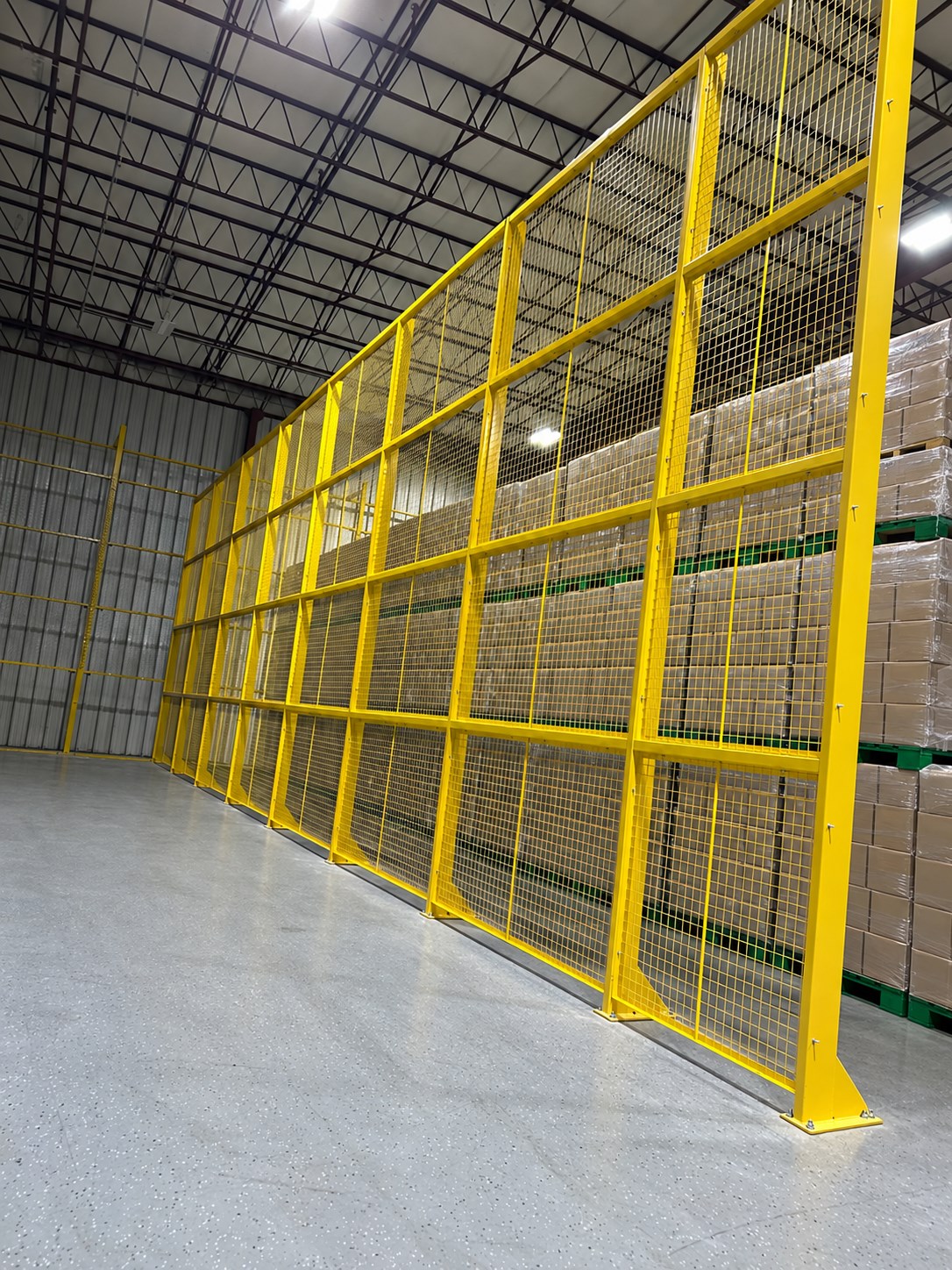
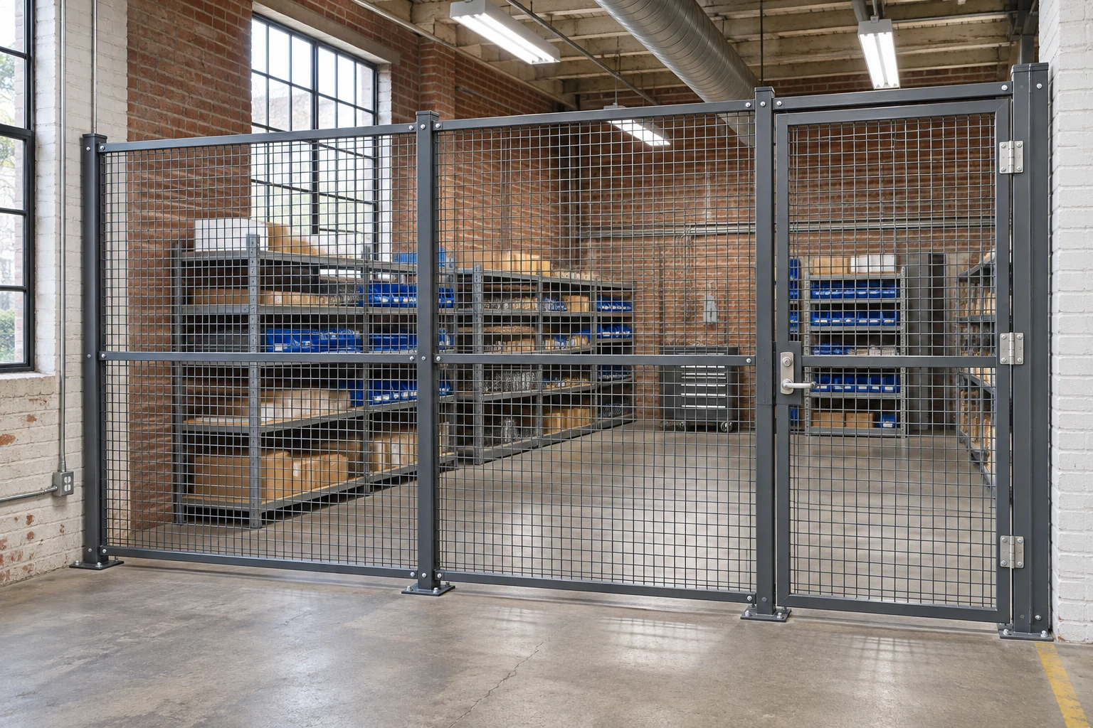
Measure a wire-mesh enclosure as a complete arrangement of panels, posts, corners and gates. Distinguish the room dimensions, proposed outside footprint and required clear openings. A nominal panel width is not automatically the usable width between posts or the opening available through a gate.
Establish a consistent measurement reference
Start with a plan that identifies the walls, floor features and fixed obstructions around the proposed enclosure. Record which surfaces the dimensions refer to and where each measurement begins and ends. A sketch with clearly identified reference points is more useful than an unexplained list of lengths.
Measure at the locations relevant to the proposed installation and note visible changes in level or alignment. Do not assume an existing wall is square or that one room measurement describes every height. Provide the observations to the supplier and installer rather than compensating for them with an improvised panel arrangement.
Separate panel sizes from system dimensions
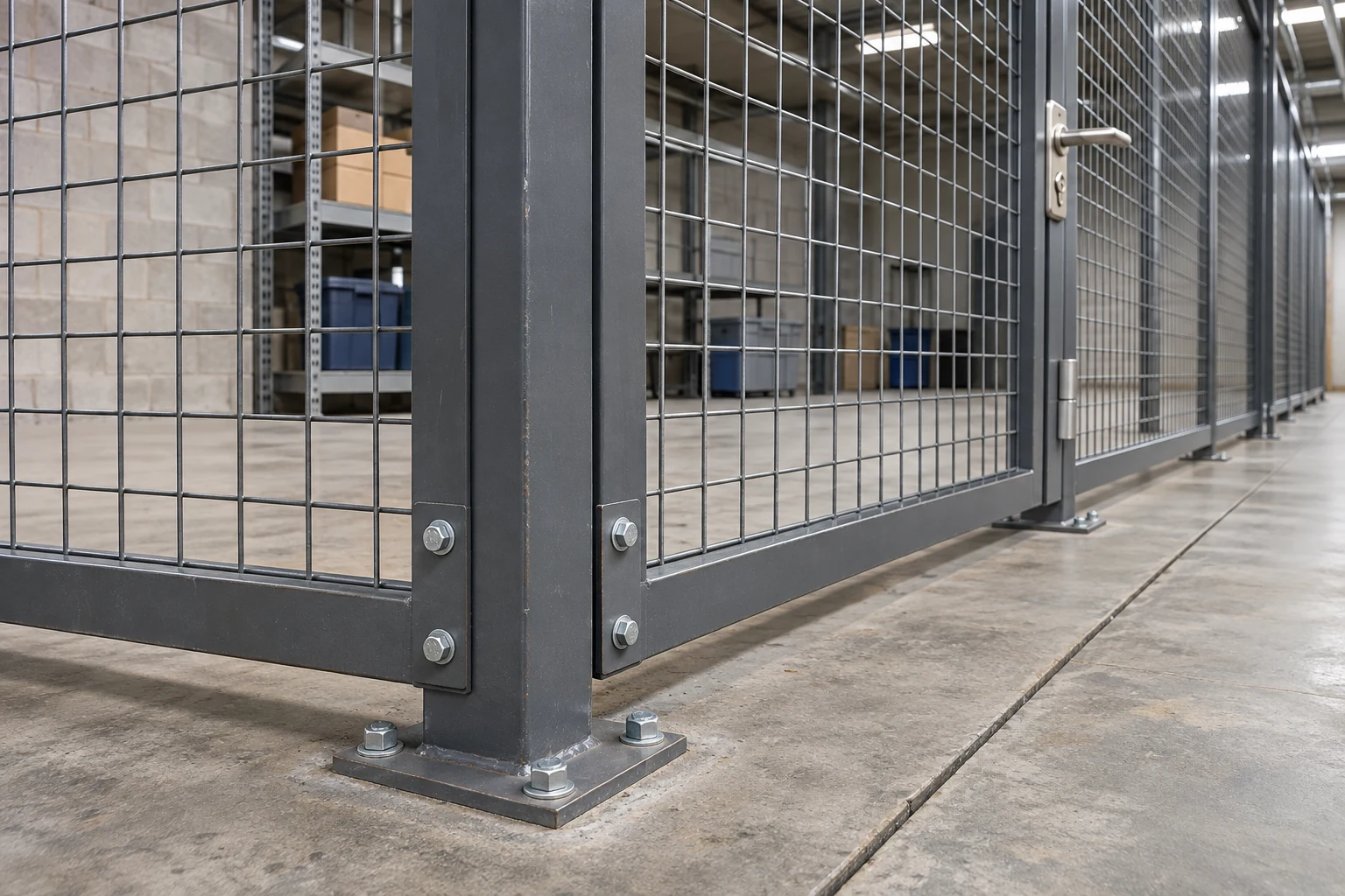
Cogan's partition panel information describes framed welded-wire components. The complete partition system combines panels with posts and gates. Ask the supplier how the specified component sizes translate into the final installed dimensions.
When a project must fit between two fixed objects, identify the maximum outside envelope and any required operating space. When people or goods must pass through an opening, identify the clear usable opening. These are different requirements and should appear separately on the plan.
| Dimension | What it describes | What to avoid assuming |
|---|---|---|
| Room dimension | Existing space between identified references | That it equals an available panel run |
| Overall enclosure | Proposed outside footprint | That posts and interfaces occupy no space |
| Panel size | A specified component dimension | That it equals every installed clear distance |
| Gate opening | Usable passage for the intended movement | That nominal gate width equals usable access |
| Height | Intended boundary and overhead relationship | That all services lie above one clear plane |
Draw corners and gate movement
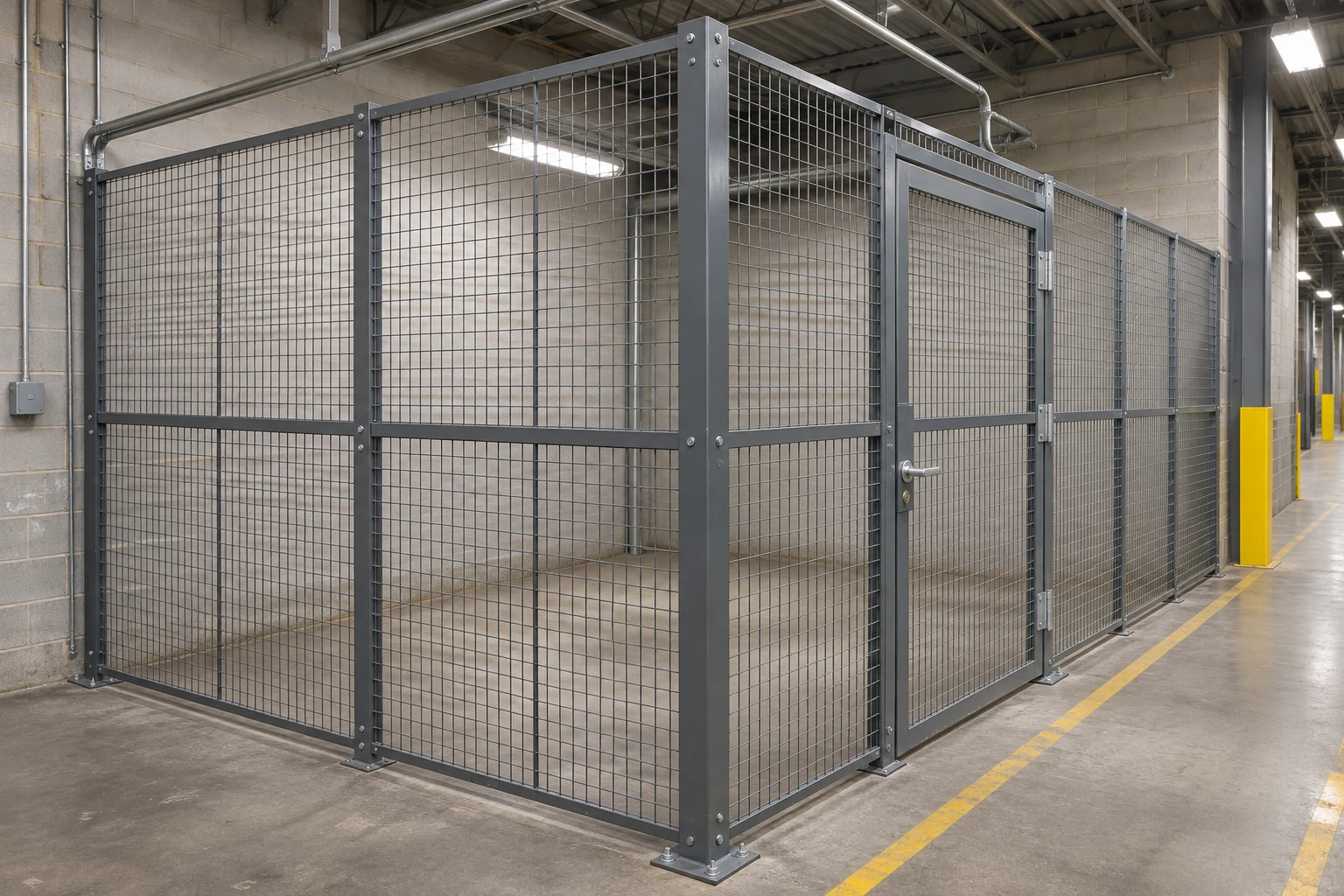
Show how each run turns a corner and how it meets existing walls or structures. Identify which side of the boundary must remain clear. A corner detail can affect both the internal usable area and the outside footprint.
For gates, include the full swing or sliding runback, the approach and the intended load or cart movement. The sliding-versus-swing guide helps describe the operating requirement. Avoid finalizing the panel count before those openings and movements are resolved.
Include overhead and floor interfaces
Record building services, doors and other features around the enclosure. Where a roof is proposed, provide an elevation and show the required maintenance access above and around it. The cage roof guide explains why the top boundary and building services should be coordinated.
At floor level, mark joints, existing anchors and known installation restrictions. Have the mounting conditions reviewed through the responsible project team. Measurements identify the site conditions; they do not establish a universal anchoring detail or authorize drilling into an unknown surface.
Send a quote package that can be checked
Provide the dimensioned plan, elevations, photographs and a short description of the intended use. Mark the dimensions that are fixed constraints and the areas where alternatives can be considered. Ask the supplier to return the proposed overall layout and component schedule for comparison with the site requirements.
Resolve discrepancies before ordering. Keep the accepted layout with the installation records so later repairs or expansions can be identified against the actual system. If components are being reused, use the relocation guide rather than assuming the old panel count will fit the new room.
Request a Cogan quote with the complete measurement package. A verified layout lets the supplier select compatible panels, posts and gates without turning an approximate room length into an unsupported component order.
Frequently asked questions
Is panel width the same as clear opening width?
Not necessarily. Component, installed-system and usable-opening dimensions describe different things. Confirm the required measurement with the supplier.
What should be included besides a floor plan?
Include relevant elevations, overhead services, gate movement, photographs, floor conditions and a description of the intended use and access requirements.
Can extra panel material simply be cut away to make the enclosure fit?
Do not assume field alteration is permitted. Resolve the fit through the approved component layout and the manufacturer's installation requirements before ordering or modifying parts.
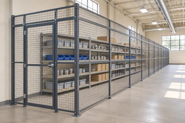
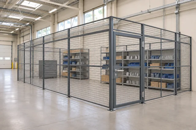
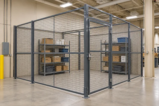
Images are conceptual product visualizations. Final configurations must follow the approved project drawings.
More on Partitions
Wire Mesh vs Drywall Warehouse Partitions: Define What the Wall Must Do
Compare mesh enclosures and drywall assemblies by visibility, privacy, sound, building services and required separation performance.
Warehouse Cage Locks: Match Gate Hardware to Access and Exit Needs
Specify wire-mesh cage lock hardware alongside gate type, occupant exit needs, key administration and maintenance.
Welded Wire vs Chain-Link Partitions: Compare the Complete Enclosure
Compare welded-wire and chain-link partitions through panel construction, framing, openings, gates and installation scope for the actual storage task.
© 2025 Cogan Wire and Metal Products Ltd., all rights reserved.